Showing posts with label soundhole patch. Show all posts

Sunday, March 2, 2008

Biggest day yet, part II

Blogger kept crashing on me near the end of the last post, so I elected to split them into two posts. If you haven't yet read about shaping the braces, read the next post before this one.

Here you can see the top and back, along with the cutoffs (which the plan suggests keeping for use as cauls later in the project). On the right are the three major components to date – the top, the sides and kerfing, and the back.


And here's an exciting photo – I stacked the parts together on the benchtop just for giggles and took a photo. At some point in the near future the instrument will be glued together like this and then the top and back will be trimmed to final shape. I just thought it would be cool to see it like this.


Since I still had several hours (at this point I had spent only about 1.5 of my 6 or so) I decided to cut out the soundhole as well. Now, the plans suggest cutting the soundhole patch using a hobby knife. I had been dreading this step because I was frankly worried that I would cut this poorly and damage the top by over cutting. It had to get done sometime, though – so here it goes.


The photo on the left shows the soundhole from the kit manufacturer with the soundhole patch glued over it. The photo on the right shows the results of the rough-in cut out (as suggested by the plans I made a first cut a bit shy of the edges of the soundhole, followed by a final cutout to actual shape). As you can see in the left photo below, I did some minor damage to the top wood surrounding the soundhole when cutting it out just as I had worried. However, the next step in the plan is to smooth and bevel the edges of the soundhole with sandpaper so I decided not to worry too much about minor damage. Fortunately the damage turned out to be very minor indeed – the photo on the right is the soundhole after smoothing and rounding with some 120 grit sandpaper (the MDF of my benchtop is also visible here, and it might make the soundhole hard to make out. Sorry.)


These last two photos are of the top after all the work of today was complete. The one on the left is of the inside of the top (the side that will not be visible after the instrument is complete). You can see the soundhole patch and the markings for all the braces in this photo. The one on the right is of the outside of the instrument.


Next time I will be sanding the kerfing to match the curvature of the top and back, and gluing in some of the braces. Not too long until the body is largely complete!


Biggest day yet

Wow! I got several hours to work in the shop today and the outcome was better than I could have imagined. My wife took the kids and went off the visit her parents, and she instructed me (this is why I know she's the right girl) to work on the mandolin. I got more accomplished today than any other day of work on it yet!

I started off by shaping the braces for the top and back. The kit includes a specially sized “sanding stick” made of ¼” plywood. They even included a little piece of the same plywood for use as a caul for clamping the stick to the benchtop. The kit designers thought this step out well, and planned for it well, too – the caul that was included for the outside of the sides at the neck block it just the right height at the edges to result in the proper radius of curvature when used to elevate the non-clamped part of the stick. The following pictures should give some idea of what the heck I'm talking about:


The photo on the left shows the stick clamped to the benchtop and propped up at the other end using the neck block caul. A clamp holds the neck block caul in place – I found that the two clamps at the bench kept the stick from rotating sufficiently. As directed by the instructions I also supported the stick at two other points along its length; one of the supports is the tail block caul and the other is a piece of scrap left over from the toolbox I built for my son for his birthday. The picture on the right shows the same setup from above just for clarity. You can see the self-adhesive sandpaper (80-grit as recommended) in the photos.
The instructions say to sand one of the braces and compare it to the drawings, adjusting the curve by moving the neck block caul in or out until the curvature is satisfactory. You then sand all of the braces using that same setup so that they are the same. I found that, by luck, my setup worked out very well the first time, so I went about sanding all of the braces to the curvature shown on the plans (which the instructions helpfully tell me is about an 8' radius).


The picture on the left is an action shot of me sanding one of the braces. I used a longitudinal motion to sand them – that is along the length of the stick and not side to side across it. This just seemed easier and the results were good, so I guess it's OK – at any rate it matched the grain direction so it made for clean sanding. The photo on the right shows the completed braces. Note that there are two #3 braces.

The next step is rough-cutting the back and top. I had not originally planned to do this today, but the shaping of the braces went so well and so quickly that I decided to have at it. The instructions say to cut the top and back with a bandsaw if you have one. Since I do I decided to give this a shot.

Up until today I had not had luck with my bandsaw, which I bought used (along with almost all of the rest of my stationary power tools) from a guy who was liquidating his shop. I examined the saw and realized that I had not been setting the damned thing up correctly. Not one of the cuts I had tried with it had been successful until today. Today I adjusted the tensioner more carefully and realized that I had not been properly adjusting the blade guide. After having done this the saw cut like a dream. Lesson learned – adjust your bandsaw carefully for each situation and it will cut much, much better.

I used the bandsaw to cut out the back and sides (the instructions tell you to leave about ¼” proud for later trimming to the actual shape of the instrument). Because I was not being very careful about accuracy since I was leaving the cut proud it went fast. I first had to mark the brace on the back and trace the outline (the left photo) and then cut it out on the bandsaw (the right photo).


Flush with my success I then cut out the top as well.


Saturday, February 23, 2008

Soundhole patch

Because of a little glitch in timing today I got to work on the mandolin again. I only did a little bit of work, but it's still nice to get out there!

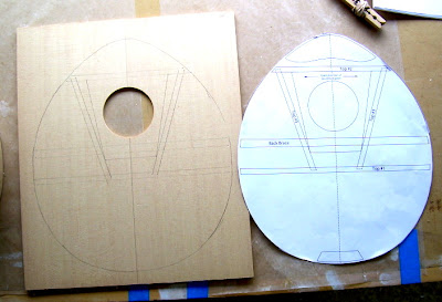
The task for today was to transfer the bracing pattern to the inside of the top and apply the soundhole patch (the soundhole patch is explained in a post below). In order to do that it was necessary to cut out one of the patterns of the top of the instrument. As an engineer I am loathe to work on an original document. I had therefore prepared for this by making photocopies of the pattern in question. Using the Xacto knife, I cut out the pattern for the top.

I then marked a centerline on the inside of the top. Using the centerline, and the soundhole already cut in the top by the kit manufacturer, I centered the cut out pattern on the top and traced around it to mark the approximate shape of the top. I then used the tip of my mechanical pencil (0.5mm!) to press through the pattern at the corners of all the braces, leaving dimples in the wood that I connected with the pencil and the straightedge to complete transferring the brace pattern (this is the method recommended by the instructions).

The final step was to glue the soundhole patch to the top. I did this using the Titebond. The instructions recommend using a weight instead of clamps for this operation - this made sense to me, so you can see the 30 cal ammo box I keep tools from my old Jeep in used as a weight. Because the bottom of the ammo box is not flat I used a cutoff of MDF, originally used as a spacer during glueup on another project (the markings on it have nothing to do with the mandolin) as a caul. A piece of waxed paper under the top, and one between the soundhole patch and the caul, prevent the top from sticking to the table and the caul.

Tuesday, January 15, 2008

Kerfing for back

On Monday I took the mandolin out of the clamps (err... clothespins) and examined my work. Here is the result of the glue-up of the kerfing for the top of the mandolin:


Here I'll take a moment to once again try to explain kerfing. I now have a couple of good examples of what it looks like in the field.


See how the kerfs in the wood (the word kerf refers to the bit of wood removed by the passing of a saw blade, so here they are the notches in the wood) allow the wood to bend smoothly while still maintaining a nice bit of glue surface on top?


Here we have two closeup details of what the kerfing looks like. Notice how the kerfs close slightly on inside curves, allowing the wood to bend smoothly.


Finally, I have a closeup of the kerfing in the clamps, showing the small amount I left the kerfing proud of the sides during the glue-up. The instructions say to make this small reveal about 1/32". No idea how close I am to that but it looks fairly good, anyway.


These last two pictures are of the glue-up underway, showing how I laid out the kerfing on the side while clamping. Also shown is a photo of the back with all clamps in place.


After this was done I had some time before my wife and boy came home. The next step in the instructions is to layout the braces on the top and back. However, it recommends cutting up the pattern to make this easier. I'm an engineer and I hate working on an original - it makes it impossible to revert - so I decided to take the pattern/drawing in to the office and make a couple of copies before cutting anything up. The next step after the layout step is to cut the soundhole patch. This step does not rely on the layout on the top so I decided to do this step instead.

The soundhole patch is a very thin piece of wood that reinforces the top at the soundhole. The top is made of bookmatched spruce - which essentially means that it is made of two identical pieces with a joint running from the tailpiece to the neck - and the soundhole patch strengthens the top in the area where the material was removed to make the soundhole. The wood is very thin - almost a veneer, really - and the intention is for the soundhole patch to have its grain run perpendicular to the grain of the top. It's trapezoidal and because the wood is very thin I cut it with my Exacto knife and a straightedge. A few moments of layout and the cuts were made.


The photo on the left shows the layout of the soundhole patch cuts, including the patch itself, the framing square I am using as a straightedge, and the drawing/pattern. The one to the right shows the soundhole patch after trimming with the straightedge and the Exacto knife. I should also take a moment to apologize for the incredibly ugly cutting mat. Darn you, Wal Mart!!!


The final image of the day shows the drawing/pattern, the soundhole patch, and the top blank. The next step, probably on Wednesday, will be to transfer the brace locations and commence to shaping the braces, and to glue the soundhole patch onto the top.